
Maslow 4.1 Upgrade Guide
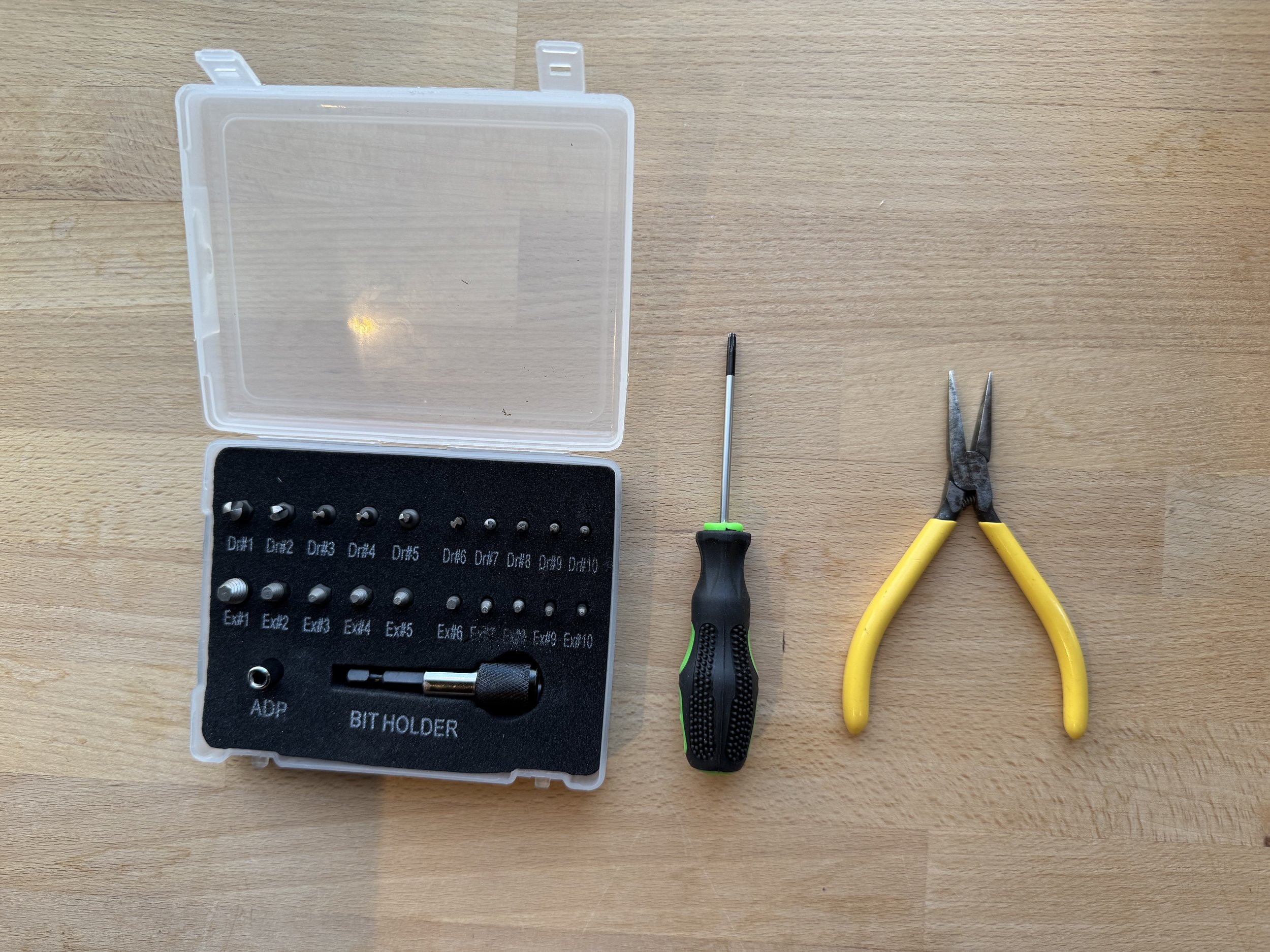
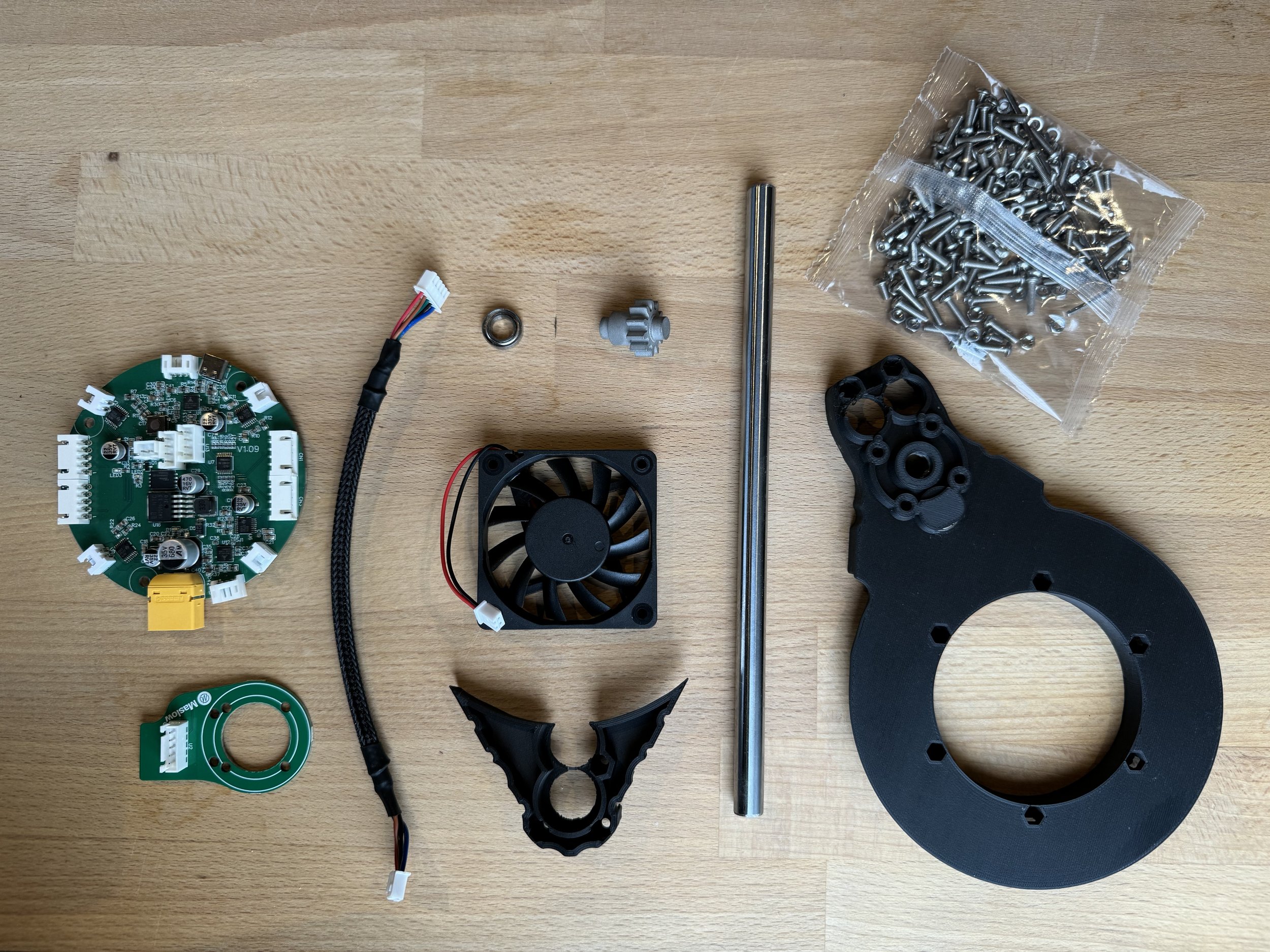
The changes in the Maslow 4.1 hardware upgrade touch many different parts of the machine…unfortunately that means we need to take a lot apart. Before getting started, here are some tools other than the included ones which you might find useful to have on hand. They include a small pair of pliers, a Torx T10 screwdriver, and a set of easy outs (I used this one) which make it easy to remove any stripped Allen bolts.
Here is a quick and dirty video overview of installing the 4.1 upgrade
This guide is a work in progress.
I am still waiting on my kit to arrive with the correct color parts so please ignore any slight differences that you see between these instructions and what is in your kit.
Since the upgrade process is very similar to the process of putting the machine together the first time I am going to focus on what is different. Feel free to consult the full assembly guide for more info.

The first step of disassembly is to remove the six bolts holding on each of the upright supports for the linear rods

Next, unplug the z-axis stepper motors from the control board and then manually rotate them to separate the body of the machine from the sled.

Remove the three bolts from each of the supports and loosen the two bolts holding the clamping wedge in place.

Remove the lower clamp.

Unplug and remove the four arms from the machine

Remove the eight bolts holding the two halves of the arm together.

Separate the two arm halves

Set aside the motor, spool and belt, belt end, rollers, drive gear, and bearings for later.

Note that the bolts holding the motor in can be difficult to remove because they have thread locker. If they strip an easy-out tool can be used to remove them.

Now we can start installing the 4.1 parts. First, we need to add bolts to the 4.1 arm. Because of some geometry tweaks in the design these will be quite tight. Us a non locking nut on the back side of the arm to help pull them into place.

With all eight bolts in place the arm should look like this

Then we need to repeat the same process on the other arm side with the lock nuts. Again, use a bolt to pull each nut into place, then remove the bolt.
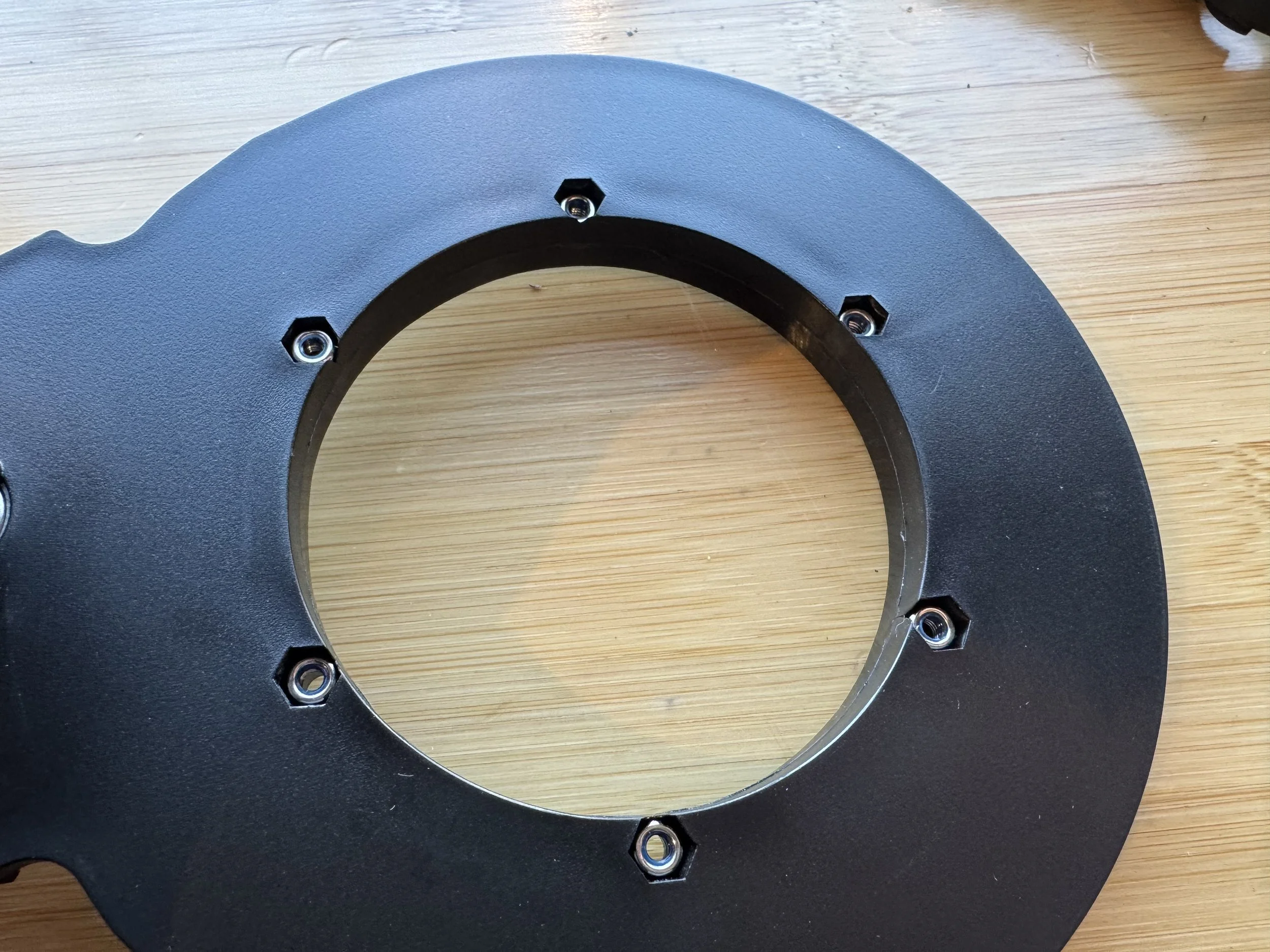
Once all six nuts are in place the arm should look like this

Next attach the encoder board and motor like before

On the other side of the motor attach the drive gear and place three bearings.

On the opposite arm, place four bearings

Attach the updated belt guard. It is held in place with three nuts and bolts from the back side of the arm.

Feed the belt through the arm and place the spool

Place the rollers, noting the position of the magnet

On the other arm, place the idler gear.

Connect the two arm hales. Note that it might takes some jiggling of the gears and other parts to get everything to slot together.
I like to start at the back furthest away from where the belt comes out and work my way forward making sure each part lines up.

Connect the belt end to the end of the belt.

Once all four arms are complete, re-attach them to the router. Here is a gif showing the correct order:

Credit to jwolter for creating this helpful image

With all four arms installed your machine should look like this

Re-attach the lower clamp

ToDo: Replace linear rods, fan, and controller board (waiting on production parts)

One other thing to note is that after making the upgrade, I was able to lower the amount of force needed to retract the belts and to take measurements during calibration to 900.
I recommend making that change too.